With over 100,000 units sold, Tides Marine SureSeal® self-aligning shaft seals are used by more US pleasure boat builders than any other. The new Tides Marine SureSeal® Series Shaft Seals has redefined the standard, offering numerous design and performance improvements.
The picture below shows the complete SureSeal System from Tides Marine.
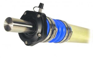
The PDF File SureSeal Parts, is a 2 page file that shows the parts used to make a SureSeal Shaft Seal. View these 2 pages to see what each part is called. Click here to open the file
The parts that can be replaced in the field are:
•Lip Seal
•Cap
•Washer
•Collar
•Injection Fitting
When placing an order for a Cap, Collar or Washer, you will need to supply either the Serial Number of the Shaft Seal or the Shaft Size and Stern Tube OD in order to get the correct sized replacement.
Key components and features of the new SureSeal® include:
Housing– Made from a new fiber-reinforced composite material, the housing is stronger, smaller and more durable than its predecessor. Dimensionally unaffected by temperature changes, the SureSeal® will not absorb water.
Bearing– The integral PTFE bearing extends the useful operating life of the SureSeal® under normal operating conditions. Should the water injection system fail to provide lubrication to the lip seal and bearing surface, the integrity of the SureSeal PTFE bearing and fiber-reinforced housing is unaffected. This feature allows the vessel operator to simply replace the worn lip seal, restoring the “100% watertight” characteristic of the SureSeal®.
Hose– Connecting the SureSeal® to the boat has been made easier via an all new ” articulating” hose. Matched to each housing size, the hose design positions the unit relative to the stern tube so that the required operating clearance is achieved without measurement (simplifying installation). This new hose greatly reduces the side loads to the SureSeal® when shaft misalignment occurs (as much as 1/4″ in any direction), extending lip seal and bearing life.
Hose Clamps– The hose clamps themselves are an improved design which won’t tear or mar the hose surface, require less tightening force and adjust to the changes in the hose diameter caused by variations in temperature and pressure.
Seal Replacement– The new design incorporates a removable front cap which allows access to the lip seal making it easier to remove and replace, especially in “cramped quarters”.
NOTE: Tides Marine SureSeals are NOT recommended for use with engines with less than 4 cylinders. The Tides Marine Series-One Shaft Seal should be used with 1, 2 and 3 Cylinder Engines
Installation Overview

The following is a brief description of a typical SureSeal® installation. Detailed instructions are included with each product and should be followed closely.
USE NO GREASE!
1.Separate shaft and shaft coupling from the transmission.
2.Remove shaft from shaft coupling.
3.The installer must clean the portion of the shaft between the inboard end and the existing sealing system.
4.Remove old sealing system. DO NOT REUSE OLD COMPONENTS. Parts will not function properly with your new SureSeal®.
5.Draw shaft back in against the transmission. This will expose that portion of the shaft that was located under the old hose and stuffing box
6.Put two hose clamps loosely onto the SureSeal® end of the hose.
NOTE: One end of the hose may be larger than the other. Insert SureSeal® unit into articulating hose as far as it will go.
7.Position the hose with SureSeal® installed next to the stern tube to determine approximately where the lip seal will ride on the shaft.
8.Examine this area carefully. Be sure that it is free of pitting, nicks or surface imperfections that could cause leaking. Clean this area thoroughly. Polish the shaft using 300 grit wet/dry sandpaper or emery cloth working around the shaft. Fore and aft actions could put flats or grooves in the shaft. In order to find the best spot to position the lip seal, may be shifted forward slightly by adjusting the position of the hose on the stern tube at time of installation.
9.Carefully press the red seal protector “hat” into the front of the SureSeal®. Make sure it covers the “lip” portion of the seal.
10.Back the shaft away from the transmission to provide enough room to install the assembly.
11.Loosely install two hose clamps over the end of the hose that installs over the stern tube. Carefully slide the assembly (hose-end first) onto the shaft so that the shaft passes through the red seal protector “hat”.
12.Slide the assembly down the shaft and onto the stern tube. Push it on as far as it will go or as needed to position the lip seal on the shaft at a clean spot. Mark the stern tube at the aft end of the hose.
NOTE: Ensure that both clamps will clamp the stern tube.
IF YOU ARE INSTALLING SPARE SEALS DO IT NOW
Click here to go to Spare Seal Installation Instructions
13.Reconnect the shaft to the shaft coupling. Make certain the shaft coupling is firmly secured to the transmission.
14.Prior to “snugging” the hose clamps, slide assembly forward and rotate back and forth then slide assembly back to mark on the stern tube. This helps align the seal to the shaft.
15.Space the two hose clamps over the hose on the stern tube evenly and “snug”. Hose clamp “screws” should be on opposite sides of the hose to distribute pressure evenly. Space two hose clamps over the hose on the SureSeal®. Snug. Visually inspect the assembly. Tighten hose clamps.
NOTE: Do not over tighten clamps as this may cause leaking.
16.Pull all the red seal protector “hats” from the SureSeal® and spare seals. Separate the tabs to split the hats and remove them from the shaft.
17.If spare seals were installed check to be sure the housing is at least 1″ from the SureSeal®. Reassemble the Spare Seal Carrier housing over the lip seal(s) and around the shaft. The long shoulder should face away from the SureSeal®. Tighten the assembly screws. Properly installed, the Spare Seal Carrier should grip the shaft tightly and turn freely with it.
18.Connect the SureSeal to a pressurized water supply source (poinmtin the engines raw water cooling system) by attaching the water injection hose to the stainless steel fitting on the housing. If there is a second hose fiting on the SureSeal, it is used to complete a crossover feed between the port and starboard shaft seals.
NOTE: DO NOT USE A CROSSOVER LINE if the highest point in the exhaust system is above the turn of the exhaust riser. “Back flow” could occur while running on only one engine causing serious damage to the other engine/turbo.
Note: Appropriate hose for this application is Type “A” or Type “B” fuel hose, or any marine grade hose reinforced for hot water applications.
CHECK WATER SUPPLY BEFORE OPERATING VESSEL
DID YOU REMOVE ALL THE RED SEAL PROTECTOR “HATS”?
Before Ordering
SureSeals® are sold with their corresponding hoses only. To determine which parts to order and whether or not you have sufficient space for their installation, you need to measure “A”, the shaft diameter and “B”, the O.D. of the stern tube (which corresponds to the hose I.D.). Find the combination of these two dimensions in the following table and the corresponding part numbers. For each model SureSeal®, find dimension “C” and confirm that there is AT LEAST this much CLEAN, SMOOTH shaft before the stern tube available for locating the unit.
Next, the diameter “D” should be noted. Confirm that a minimum distance of 1/4 inch can be maintained between the body of the unit and any other part of the boat (hull, stringers, etc.) to allow for any lateral shaft movement.
In twin-engine applications, SureSeals® may be ordered with an optional “second injection fitting” to accommodate a crossover line between Tides Marine SureSeals®.

If you want your unit to have one injection fitting, please make the last digit of the part number “0”. For two injection fittings @ 90 degrees please make the last digit “1”. For two injection fittings @ 45 degrees make the last digit “2”. For two injection fittings @ 120 degrees make the last digit “3”. (Seals for shafts 3″ and larger all have two fittings @ 90 degrees)